Input Files with SMR
Documentation/UserGuide/SMR Input Files
Multiple Domains at different levels of refinement are specified at run time using the <domain> blocks
in the input file (see Domain Blocks in the User Guide for more details).
Initializing Two Levels
As an example, consider setting up a 2D calculation on a 14x9 root Domain, with a single level=1 Domain with 8x8 cells that is offset from the left and bottom boundaries of the root Domain by 5 and 3 root Domain cells respectively (for simplicity the size of this Mesh is ridiculously small on purpose). The image below shows the desired Mesh.
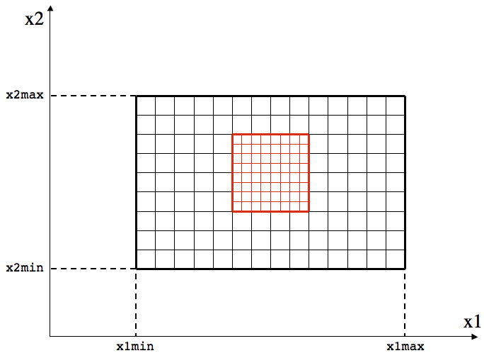
This Mesh configuration can be initialized with the following two Domain blocks in the input file.
<domain1>
level           = 0         # refinement level this Domain (root=0)
Nx1             = 14        # Number of zones in X-direction
x1min           = -0.5      # minimum value of X
x1max           = 0.5       # maximum value of X
bc_ix1          = 4         # boundary condition flag for inner-I (X1)
bc_ox1          = 4         # boundary condition flag for outer-I (X1)

Nx2             = 9         # Number of zones in Y-direction
x2min           = -0.5      # minimum value of Y
x2max           = 0.5       # maximum value of Y
bc_ix2          = 4         # boundary condition flag for inner-J (X2)
bc_ox2          = 4         # boundary condition flag for outer-J (X2)

<domain2>
level           = 1         # refinement level this Domain (root=0)
Nx1             = 8         # Number of zones in X1-direction
Nx2             = 8         # Number of zones in X2-direction
iDisp           = 10        # i-displacement measured in cells of this level
jDisp           = 6         # j-displacement measured in cells of this level
The position of the level=1 Domain is determined by the iDisp and jDisp parameters in the
<domain2> block, and these positions are measured in units of the grid cells at the level of
the <domain> block that specifies them (in this case level=1).
Initializing Two level=1 Domains
Now consider setting up a 2D calculation on a 18x14 root Domain, with two level=1 Domains each with 12x12 cells. The first level=1 Domain is offset from the left and bottom boundaries of the root Domain by 2 and 3 root Domain cells respectively, while the second is offset by 10 and 4 root Domain cells respectively. The image below shows the desired Mesh.
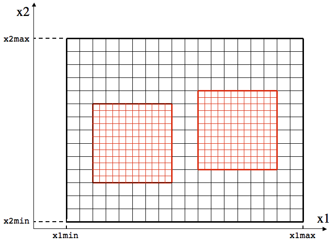
This Mesh configuration can be initialized with the following two Domain blocks in the input file.
<domain1>
level           = 0         # refinement level this Domain (root=0)
Nx1             = 18        # Number of zones in X-direction
x1min           = -0.5      # minimum value of X
x1max           = 0.5       # maximum value of X
bc_ix1          = 4         # boundary condition flag for inner-I (X1)
bc_ox1          = 4         # boundary condition flag for outer-I (X1)

Nx2             = 14        # Number of zones in Y-direction
x2min           = -0.5      # minimum value of Y
x2max           = 0.5       # maximum value of Y
bc_ix2          = 4         # boundary condition flag for inner-J (X2)
bc_ox2          = 4         # boundary condition flag for outer-J (X2)

<domain2>
level           = 1         # refinement level this Domain (root=0)
Nx1             = 12        # Number of zones in X1-direction
Nx2             = 12        # Number of zones in X2-direction
iDisp           = 4         # i-displacement measured in cells of this level
jDisp           = 6         # j-displacement measured in cells of this level

<domain3>
level           = 1         # refinement level this Domain (root=0)
Nx1             = 12        # Number of zones in X1-direction
Nx2             = 12        # Number of zones in X2-direction
iDisp           = 20        # i-displacement measured in cells of this level
jDisp           = 8         # j-displacement measured in cells of this level
Note that 2 root level cells are required between the two level=1 Domains.
Initializing Three Levels
As a final example, consider setting up a 2D calculation on a 9x7 root Domain, with a single level=1 Domain with 8x6 cells, and a single level=2 Domain with 8x4 cells. The first level=1 Domain is offset from the left and bottom boundaries of the root Domain by 3 and 2 root Domain cells respectively, while the level=2 Domain is offset by 4 and 3 root Domain cells respectively. The image below shows the desired Mesh.
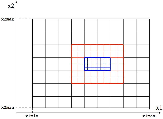
This Mesh configuration can be initialized with the following two Domain blocks in the input file.
<domain1>
level           = 0         # refinement level this Domain (root=0)
Nx1             = 9         # Number of zones in X-direction
x1min           = -0.5      # minimum value of X
x1max           = 0.5       # maximum value of X
bc_ix1          = 4         # boundary condition flag for inner-I (X1)
bc_ox1          = 4         # boundary condition flag for outer-I (X1)

Nx2             = 7         # Number of zones in Y-direction
x2min           = -0.5      # minimum value of Y
x2max           = 0.5       # maximum value of Y
bc_ix2          = 4         # boundary condition flag for inner-J (X2)
bc_ox2          = 4         # boundary condition flag for outer-J (X2)

<domain2>
level           = 1         # refinement level this Domain (root=0)
Nx1             = 8         # Number of zones in X1-direction
Nx2             = 6         # Number of zones in X2-direction
iDisp           = 6         # i-displacement measured in cells of this level
jDisp           = 4         # j-displacement measured in cells of this level

<domain3>
level           = 2         # refinement level this Domain (root=0)
Nx1             = 8         # Number of zones in X1-direction
Nx2             = 4         # Number of zones in X2-direction
iDisp           = 16        # i-displacement measured in cells of this level
jDisp           = 12        # j-displacement measured in cells of this level
Once again, note that the iDisp and jDisp parameters in the
<domain3> block are measured in units of the grid cells at the level of
the <domain> block that specifies them (in this case level=2).