MAKEGRID
The MAKEGRID code computes the external magnetic field due to field coils used for free boundary runs of the VMEC code. Specifically it computes the magnetic field on a grid at specific toroidal angles. This results in the generation of the 'mgrid' file used by VMEC to compute the influence of external coils on the plasma.
Theory
The MAKEGRID code generates magnetic field data on R-Z grids at specific toroidal intervals based on a coil definition file and the Biot-Savart law. The coils file contains a sequence of points in cartesian space which define segments of wire. In essence, they define the coil in terms of a patch line. In addition to x, y, and z data, a current is specified for each segment. The last segment of each line should have zero current, a group number, and a name. The group number allows the coils to be grouped by similar currents. The names are simply used as labels for runtime output. In this way coils which carry the same current (are on the same circuit or are symmetric) may be modified with one current value. The values of the currents in the 'coils' file are simply a reference as the fields generated by MAKEGRID are normalized to a unit current.
The MAKEGRID code uses the Biot-Savart law to calculate the contribution of each coil segment to a given point on the grid. This is done for each coil group assuming unit current. The resulting field for a given coil group may then be multiplied by a different current to generate it's field. This allows codes which use the 'mgrid' file (generated by MAKEGRID) to examine different current configurations without recalculating the magnetic field on the grid. The user may also turn off a given current group by setting it's current to zero (usually handled by the EXTCUR array in an input namelist).
Compilation
The MAKEGRID code is compiled as part of the STELLOPT suite of codes. To compile XGRID please examine the STELLOPT Compilation page.
Input Data Format
The MAKEGRID code may be run interactively, via fortran namelist, or completely via the command line. The code requires a coils file which specifies the magnetic coils from which the magnetic field is calculated.
When run interactively the code will prompt the user for ten items:
- Coils file suffix
- Current format (S/R : Scale current to unit current or use raw currents, old version did not prompt the user for this and assumed scaled current)
- Stellarator Symmetry (T/F)
- Minimum radial extent (Rmin)
- Maximum radial extent (Rmax)
- Minimum vertical extent (Vmin)
- Maximum vertical extent (Vmax)
- Number of toroidal cutplanes (per half period if stellarator symmetry is assumed)
- Number of radial grid points
- Number of vertical grid points
One may also place each of these ten items on the command line. Alternatively the user can also place all 10 items on separate lines in a text file and redirect the files on the command line.
The code may also be run using the MGRID_NLI namelist provided in an input file. The namelist has the form
&MGRID_NLI
  TASK = 'MGRID'
  MGRID_EXT = 'testcoil' ! For file coils.testcoil
  MGRID_MODE = 'S'       ! (S)caled or (R)aw
  LSTELL_SYM = T         ! Enforce flip-mirro symmetry
  RMIN = 0.45            ! Minimum R extent of grid [m]
  RMAX = 1.05            ! Maximum R extent of grid [m]
  ZMIN =-0.30            ! Minimum Z extent of grid [m]
  ZMAX = 0.30            ! Maximum Z extent of grid [m]
  KP   = 32              ! Number of toroidal planes
  IR   = 201             ! Number of R gridpoints
  JZ   = 201             ! Number of Z gridpoints
/
The coils file suffix is simply the suffix for the coils file. New versions of the code allow the user to scale all currents to unit current (S) or use the raw current (found from the coils file) in the calculations of the fields. If the users chooses Scaled (S) currents then when running VMEC the user would supply the actual coil currents used in the machine (this may be the current per turn for multi-filament coils or total current for single filament coils). If the user chooses Raw (R) currents then when running VMEC the user would supply a multiple of the current found in the coils file (1 for using the current in the coils file, 0.5 for half the current and so on). If stellarator symmetry is assumed then only the first half of the toroidal cuts are calculated, the field is then mirrored for the rest of the calculation to save computation time. The Rmin, Rmax, Zmin, and Zmax specify the radial and vertical extents in [m]. Remember that the grid plane must be large enough to contain the whole plasma in each cross section. The number of toroidal cut planes indicates the number of individual planes per field period to calculate the field on. A good rule here is to choose at least 4 times as many cut planes as the maximum toroidal mode number (ex. if ntor=6 then you should have at least 24 cut planes). The choice of the number or radial and vertical gridpoints is not as straightforward. The VMEC code uses these grids to 'deform' the plasma boundary in a iterative sense. The complication revolves around the spectral condensation VMEC preforms in the poloidal direction. The code calculates the location of the poloidal grid points so that an optimized choice is made for the form of the plasma (more point where needed, points, and less where they're not, straight segments). The user should decide how accurately the wish to know the plasma boundary. If [cm] precision is required then the number of grid points chosen should provide at least this resolution. Remember that the more datapoints, the longer the MAKEGRID run and the slower VMEC will run.
The coils file is a standard filament format which has it's origin in coil design software. The first line indicates the number of field periods for a run. The next line indicates the beginning of the filament section. The third line is read by MAKEGRID but ignored. Then the definition of a coil begins. The coils is specified by connecting points in space along a line defining a coil. For each point a current is specified. The last point should correspond with the first in a given loop and have zero current. In the following example, a square coil is specified.
periods 3
begin filament
mirror NIL
0.0   0.0   0.0   5.0
1.0   0.0   0.0   5.0
1.0   1.0   0.0   5.0
0.0   1.0   0.0   5.0
0.0   0.0   0.0   0.0   1   SQ
end
The last line also contains a number which associates this coil with coilgroup 1 and a name 'SQ.' The fields from all coils of the same coilgroup will be summed. In a sense, the user can think of coilgroups as indicating common (or coupled) power supplies.
Execution
The MAKEGRID code (executable name xgrid) may be executed interactively or the user may pass a command script via the command line (see the VMEC Free Boundary Tutorial for and example).
> ~/bin/xgrid < input_xgrid.dat >& log_xgrid.coil_suffix &
or if input_xgrid.dat contains the MGRID_NLI namelist:
> ~/bin/xgrid input_xgrid.dat
Output Data Format
The MAKEGRID code creates two output files (three if the user redirects screen output to a log file). The first is the 'mgrid' file. This file contains the magnetic field generated by each coil group along with magnetic measurements if they were included in the 'coils' file. The 'mgrid' file is binary in older versions of the code, newer versions support both binary and netCDF output. The second file is the 'extcur' file. This file contains a suggestion for coil group currents based on the values found in the 'coils' file. These values can be copied to the VMEC 'input' file.
The 'mgrid' file is organized so that the contribution from each coil group to the net magnetic field is stored separately. While the methodology for reading a binary file will vary by environment, the Fortran routine 'read_mgrid.f' in '.../VMEC2000/vsource/' does provide a basic outline. The read statements from the codes (in order) are retraced below (for the magnetic field only)
       read(iunit,iostat=ierr) nr0b, nz0b, np0b, nfper0, nextcur !n_radial,n_vertical,n_toroidal,n_fieldperiod,n_extcur
       read(iunit,iostat=ierr) rminb, zminb, rmaxb, zmaxb        !R_min,Z_min,R_max,Z_max
       read(iunit,iostat=istat) (curlabel(n),n=1,nextcur)        !Read each Current Group Label
       do ii = 1,nextcur                                         !nbvac=nr0b*nz0b*np0b Total number of gridpoints
          read(iunit) (btemp(i,1,ii),btemp(i,2,ii),btemp(i,3,ii), !Read Magnetic field generated by
      1                i=1,nbvac)                                   !each current group on each toroidal cut plane
       enddo
Users interested in the inclusion of magnetic diagnostics in the 'mgrid' file should examine the 'read_mgrid.f' routine. For netCDF files the user can use the ncdump utility to see the contents for example:
    netcdf mgrid_c09r00 {
    dimensions:
        stringsize = 30 ;
        external_coil_groups = 10 ;
        dim_00001 = 1 ;
        external_coils = 10 ;
        rad = 201 ;
        zee = 201 ;
        phi = 24 ;
    variables:
        int ir ;
        int jz ;
        int kp ;
        int nfp ;
        int nextcur ;
        double rmin ;
        double zmin ;
        double rmax ;
        double zmax ;
        char coil_group(external_coil_groups, stringsize) ;
        char mgrid_mode(dim_00001) ;
        double raw_coil_cur(external_coils) ;
        double br_001(phi, zee, rad) ;
        double bp_001(phi, zee, rad) ;
        double bz_001(phi, zee, rad) ;
        double br_002(phi, zee, rad) ;
        double bp_002(phi, zee, rad) ;
        double bz_002(phi, zee, rad) ;
        double br_003(phi, zee, rad) ;
        double bp_003(phi, zee, rad) ;
        double bz_003(phi, zee, rad) ;
        double br_004(phi, zee, rad) ;
        double bp_004(phi, zee, rad) ;
        double bz_004(phi, zee, rad) ;
        double br_005(phi, zee, rad) ;
        double bp_005(phi, zee, rad) ;
        double bz_005(phi, zee, rad) ;
        double br_006(phi, zee, rad) ;
        double bp_006(phi, zee, rad) ;
        double bz_006(phi, zee, rad) ;
        double br_007(phi, zee, rad) ;
        double bp_007(phi, zee, rad) ;
        double bz_007(phi, zee, rad) ;
        double br_008(phi, zee, rad) ;
        double bp_008(phi, zee, rad) ;
        double bz_008(phi, zee, rad) ;
        double br_009(phi, zee, rad) ;
        double bp_009(phi, zee, rad) ;
        double bz_009(phi, zee, rad) ;
        double br_010(phi, zee, rad) ;
        double bp_010(phi, zee, rad) ;
        double bz_010(phi, zee, rad) ;
    }
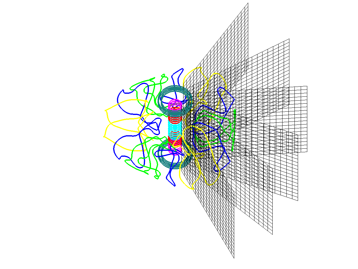
Visualization
The magnetic field data stored in the 'mgrid' file is stored for each toroidal cut and for each current group. In order to obtain the 'net' magnetic field, the user must sum the magnetic field over the current groups at each point on the grid. Additionally, these magnetic fields may have been normalized to unit current. The magnetic field from each current group must then be multiplied by the current for that group.
The matlabMAKEGRID package contains routines for reading the mgrid and coils file, along with routine for plotting their contents. It is available through the MATLAB File Exchange (http://www.mathworks.com/matlabcentral/fileexchange/29810-matlabmakegridvmec).