NMORPH
The NMORPH code calculates the PIES background coordinates from a set of surfaces and an EXTENDER calculation of the field.
Theory
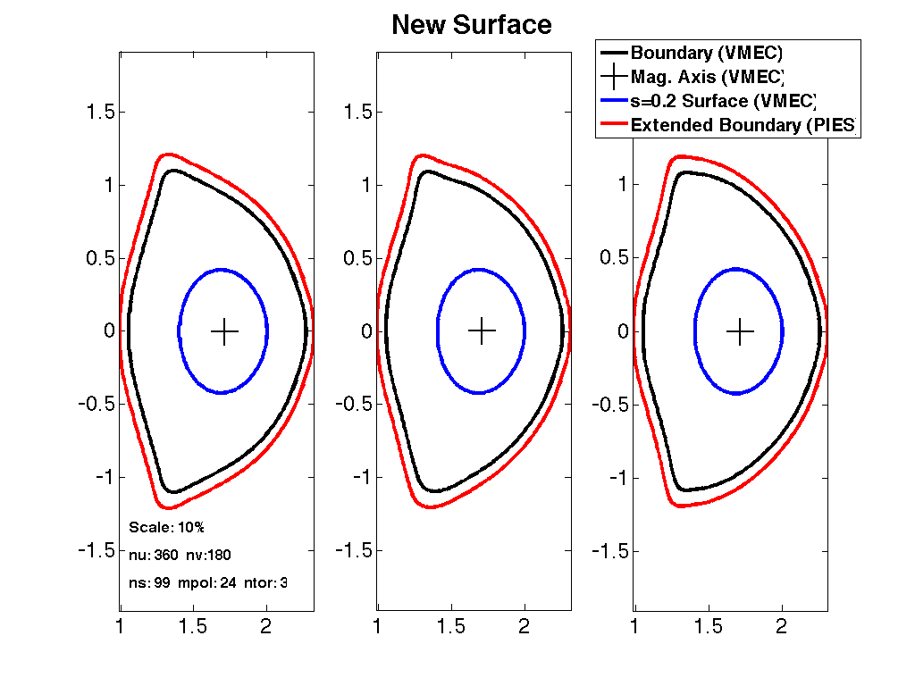
The NMORPH code calculates a set of background coordinates for the PIES code given an existing equilibrium. The code uses an optimization routine for calculation of the nested background coordinates given the Fourier specification of the outer boundary (and optionally an inner surface). Fields are calculated using the Biot-Savart law for the vacuum field and an EXTENDER output for the plasma field. The resulting output are the RZ, BUP, and mode selection matrix for the PIES input file. Below is an example of a VMEC equilibrium being used to generate input for an NMORPH run.

Compilation
The NMORPH code uses a make script to compile the code. The code requires NAG libraries, netCDF libraries, and MPI libraries. NMORPH is written in C++ and has made extensive use of MPI and object oriented programming.
Input Data Format
The NMORPH code uses command line arguments to control input
NMORPH -a <AXIS_FILE> -dom <BOUNDARY_FILE> -i <IBOUNDARY_FILE> -g<EXTENDER_MESH> -cf <EXTENDER_FIELD>
-h2 <HINT2_FILE> -hp <HINT_FILE> -hv <HINT2_VAC_FILE> -hm <HINT2_MFBE_FILE> -c <COILS_FILE> -p <PIES_FILE>
-s<NSURF>-m_use <MPOL>-n_use <NTOR> -m_hold <MPOL_HELD> -n_hold <NTOR_HELD> -h <MODULATION_HARMONICS>
-r <REFINEMENTS> -mi <MAJOR_ITERATIONS> -mmo <MAX_M_OPT> -cao <COMP_AXIS_ORDER> -digits <OUTPUT PRECISION>
|| Argument || Default || Description || || -a || || Axis file (toroidal harmonics) || || -dom || || Boundary file (Fourier harmonics) || || -i || || Internal surface file (Fourier harmonics) || || -g || || EXTENDER extended_mesh file || || -cf || || EXTENDER extended_field file || || -h2 || || HINT2 File || || -hp || || HINT File (usage: -hp <HINT_FILE>-<VAC_FILE>[TIMES<FACTOR>]) || || -hv || || HINT2 Vacuum File || || -hm || || HINT2 MFBE File || || -c || || Coils File || || -p || || PIES File || || -s || || Number of radial surfaces || || -m_use || || Number of poloidal modes || || -n_use || || Number of toroidal modes || || -m_hold || || || || -n_hold || || || || -h || 2 || Radial number of Fourier modes used to module coordinate system. || || -r || 2 || Number or refinements. || || -mi || 3 || Number of major iterations of the optimizer. || || -mmo || || Restricts the coordinate optimizer to lower order of modes. || || -cao || || || || -digits || || ||
The NMORPH code utilizes the boundary file to calculate a set of nested surfaces. These surfaces are constrained by the boundary. They may be further constrained by the axis and internal boundary specifications if provided. The code calculates the magnetic field provided the quantities passed to it via the command line arguments. If the coils file is the only provided field source the vacuum field will be calculated on the surfaces and decomposed into it's Fourier modes. To provide the total field, the user must provide the EXTENDER extended_mesh and extended_field files produced with the -plasmafield option. The user could also provide just the EXTENDER outputs with the total field (but this would be a computationally expensive run of EXTENDER). In general, NMORPH will superimpose all supplied sources of magnetic field.
Execution
The NMORPH code is executed from the command line with the proper command line parameters passed to it
NMORPH -a axis.test -dom boundary.test -i iboundary.test -g extended_mesh -cf extended_field -c coils.test -s 99 -m_use 8 -n_use 6
Output Data Format
The NMORPH code outputs three files: rz_morphed, bup_morphed and sel_morphed. The rz_morphed file contains the Fourier harmonics for the calculated surfaces. This file contains the R coefficients then Z coefficients for each surface. So the file is read R(s=1) Z(s=1) R(s=2) Z(s=2)......and so on. The bup_morphed file contains the Fourier Harmonics for the contravariant magnetic field components on each surface. In contrast to the rz_morphed file, the bup_morphed file is written Bs, Bu, and Bv in order, for example Bs(s=1) Bs(s=2).…Bs(s=n) Bu(s=1) Bu(s=2)...Bu(s=n) Bv(s=1) Bv(s=2).…Bv(s=n). The sel_morphed file contains the PIES mode selection matrix. For each radial surface the Fourier components of a quantity are written with each toroidal mode (starting from -2*n_tor) on a new line and the poloidal modes (starting with m=0) written on the line.
Visualization
Explain how to visualize the data.
Tutorials
Put links to tutorial pages here.